Peripheral Crate Electronics
Testing,
Installation and Commissioning Procedures
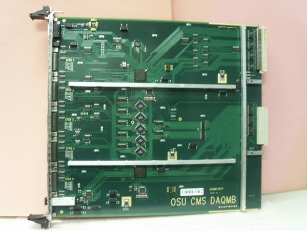
This photo shows the DMB component
side. Front to left and back to right. Note the ID sticker on the board just above
the ‘OSU …’ silk screen. Also the two alignment
pins at the rear of the board.
1.3.4 DMB
Visual Inspection and mechanical corrections –
1.3.4.1 Labeling
- The DMB do not have a serial number on the front panel. Labels must be made and attached to the front
panel of each DMB.
The labels are DYMO – 9mm – Black print
on White tape
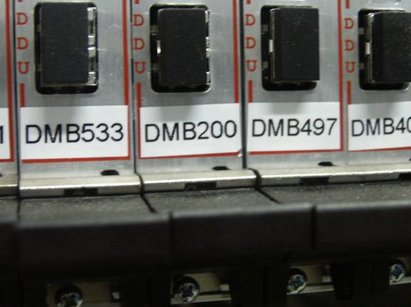
and are applied at the very bottom of the
front panel as shown in the photo. The
length must be hand trimmed to be just shorter than the width of the panel. The ID number format is ‘DMBnnn’
and must correspond to the serial number on the label on the board. Please see top photo for location.
1.3.4.1Inspect and Correct press fit pin guide
at back of board – On many boards either or both of the press fit pin guides
are not pushed in fully. Check each
board for properly pressed in guides.
When there is a gap between the guide and the board surface the guide
must be pressed completely into the board.
To do this use a large channel lock pliers. Place the pliers over the rear of the board so
that it presses on the top of the guide and the outside of the board under the
guide. See the arrows in the photo.
Squeeze firmly to press the guide into contact with the board
surface. Then tighten the Philips head
screw.

![]()
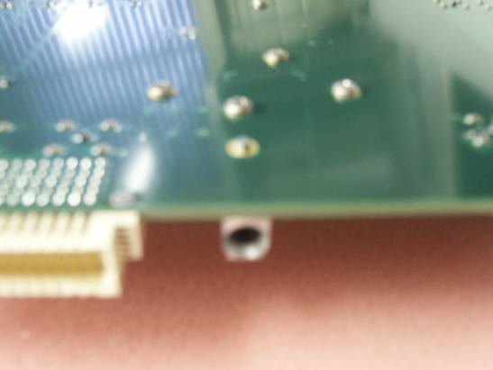
This photo was taken from the rear of the board showing the
board edge and the press fit guide. The
guide is connected to the board by a press fit pin, in the forground
and a Philips head screw in the background.
------------------------------------------------------------------------------
PCProceduresPage1-DMBMech.htm 11-March-2006 Fred Borcherding